Archives: Opera
Un’opera al museo
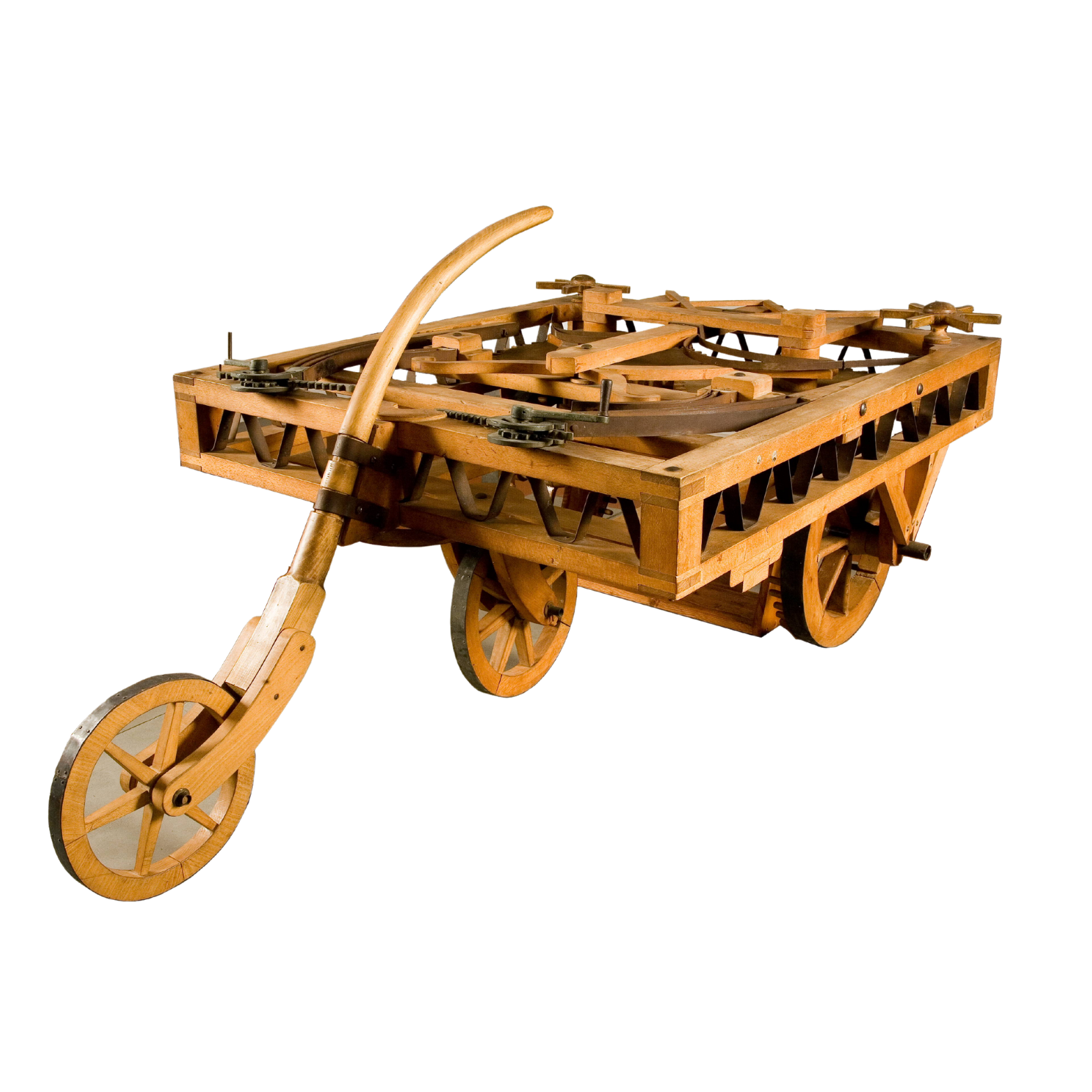
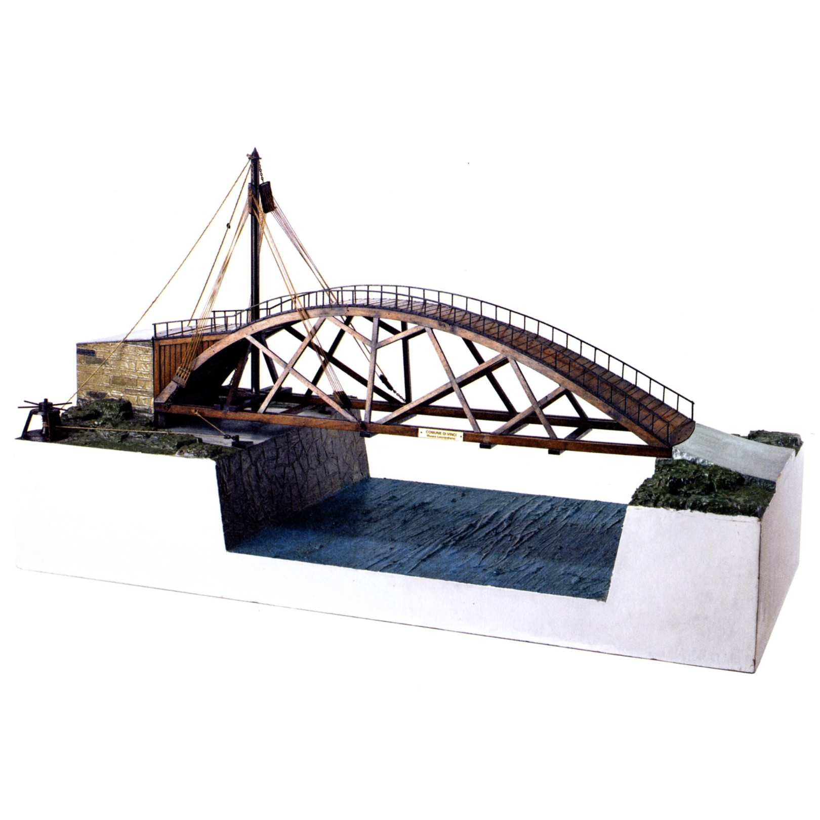
Leonardo’s notes contain numerous projects aimed at solving the problems related to crossing waterways; the technical solutions he adopted are astonishing for their modernity and ingenuity.
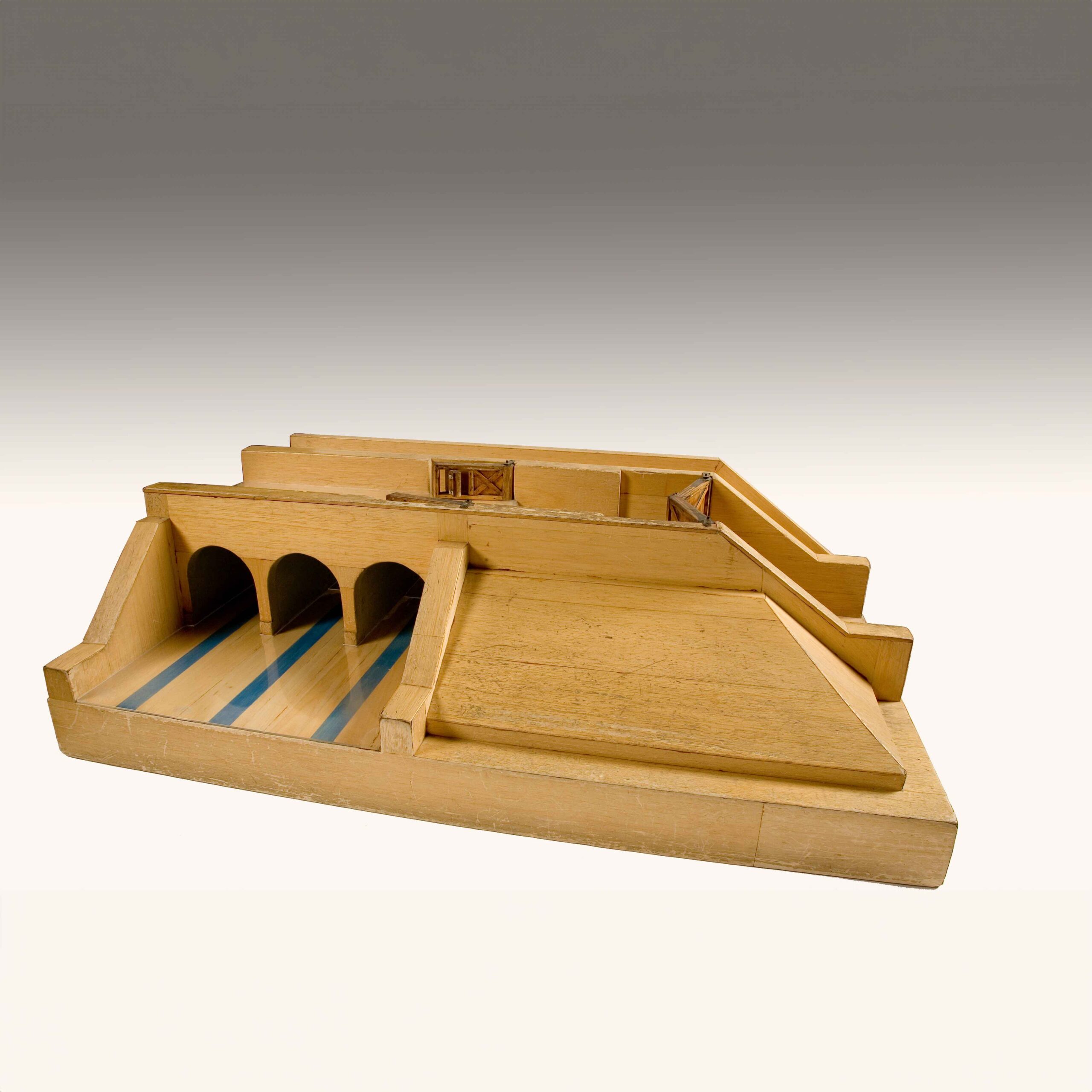
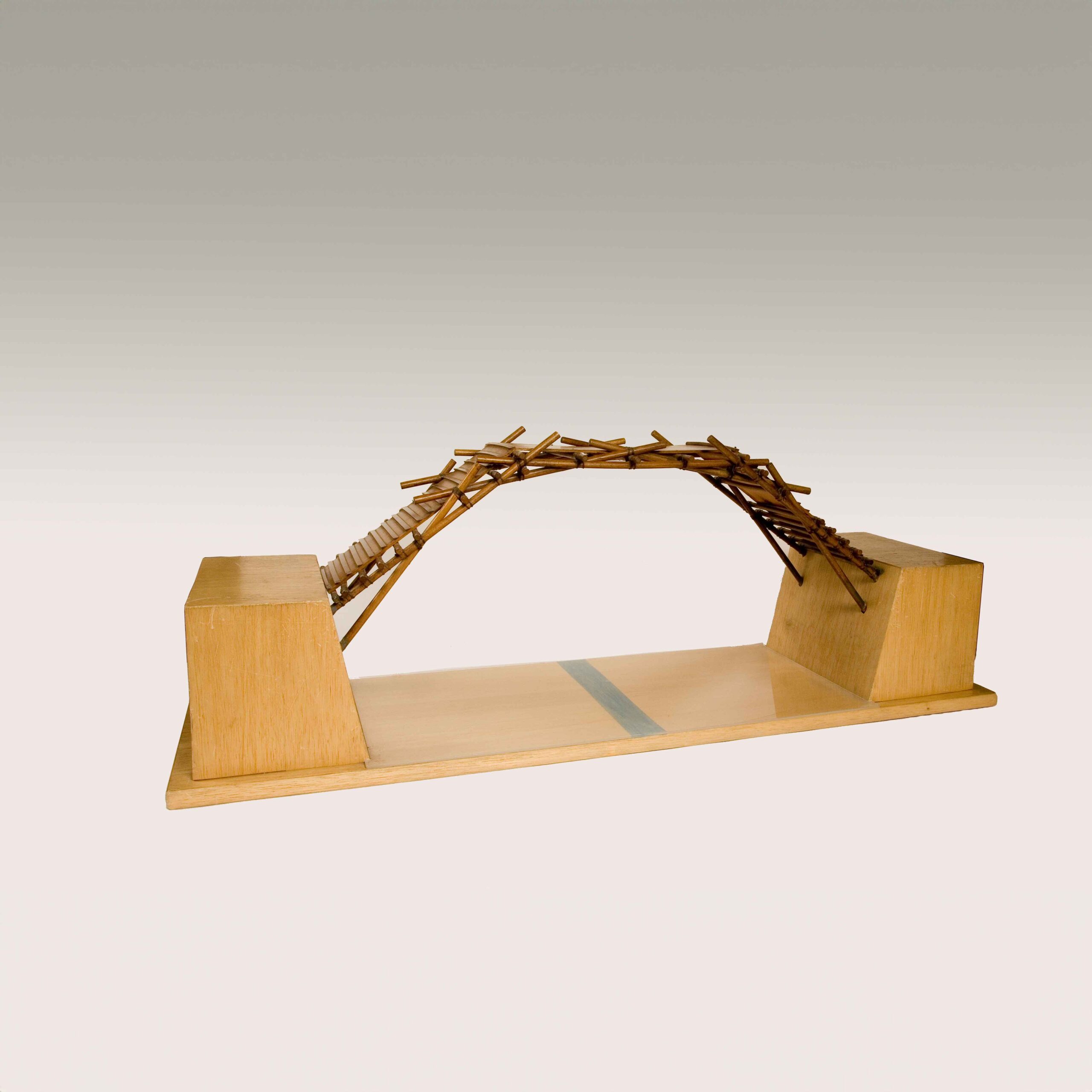
In Manuscript B, folio 23 r, Leonardo draws a bridge composed of two superimposed roadways, which allow the crossing of a watercourse on two different levels.
The two roadways are connected by inclined crossbeams arranged in a Saint Andrew’s cross pattern and joined at their ends, forming a sort of lattice of vertical diamond shapes reinforced by a diagonal beam running upward. The upper deck rests on horizontal crossbeams inserted at the intersection point of the inclined struts.
The pressure exerted by the weight of the crossbeams causes the diagonal arms to expand and withstand the load they must bear, making the bridge, as Leonardo writes, truly “unbreakable.”
Technical informations
Last update: 18 November 2025, 12:25